Keller OEM Sensors, Transducers Series 2 / 3 / 4 Piezoresistive pressure sensors for absolute, gauge and differential pressure
The pressure sensors Series 2, 3 and 4 are suited for direct-mounting on printed circuit boards. The pressure sensor is a piezoresistive measuring cell consisting of a glass back plate and the silicon chip with the diffused resistor bridge. The cell is mounted on a glass feed through and packaged in a housing for easy pressure connection. The high, stable and reliable output signal of the sensor can easily be conditioned with standard ampliiers. All sensors are tested for temperature, stability and linearity and are delivered with an individual calibration sheet.
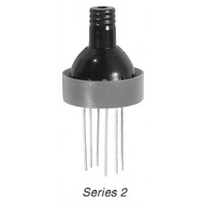
Series 2
The medium is acting directly on the silicon chip and comes into contact with the strain gauges of the Wheatstone bridge. Application in dry air only.
Series 3
The sensor is mounted in an aluminium housing. Housing and sensor are protected by a thin (7 |ìm) parylene layer. This layer grants full protection in applications where condensation may occur. Continuous water exposure is not recommended. The average time of water resistance of the parylene layer is 6 months.
Series 4
The medium acts on the rear side of the silicon chip. The pressure medium may be wet. Applications in gas, water and non-agressive luids with benign reference atmosphere. Ideal for negative pressure measurements.
Speciications
General Characteristics: Excitation I = 1 mA constant current
Ranges (FS) bar -0,1 -0,2 -0,5 -1 0,1 0,2 0,5 1 2 5 10 20
PR PR-PAA-PD PR-PAA-PA-PD
Series 2
Series 3
PR-PAA-PA
Series 4
PR-PD
PAA: Absolute, Zero at vacuum PA: Absolute, Zero at ambient (sealed gauge) PR: Gauge PD: Differential
Ranges, Overpressure, Output Signal (FS)
Pressure Ranges (FS) bar -0,1 -0,2 -0,5 -1 0,1 0,2 0,5 1 2 5 10 20
Overpressure bar -1,0 -1,0 -1,0 -1 2,5 2,5 2,5 2,5 3 7,5 15 30
Output Signal, typ. (Series 2/3) mV 18 25 45 70 18 28 58 90 135 200 200 200
Output Signal, typ. (Series 4) mV 18 25 45 70 18 25 45 70 100 150 - -
(b)
Electrical Characteristics (at 25 !aC
------------------------------------------------------------------------- 289
(a)
PR-2/1 bar/8750.8
Bridge Resistance 3500 !à 20
----------------------------------------------------------------------------------
(c) (d) (e) (f) (g)
Temp Zero +220 Comp dZero
(1)
Constant Current Excitation mA 1 max. 4,5
[!aC [mV] [mV] [mV] [mV]
0.1 -13.0 -22.5 0.1 -0.2
Isolation / 500 V M 100
25.3 -11.9 -22.3 0.3 0.0
50.3 -10.8 -22.4 0.2 -0.2
------------------------------------------------------------------------------
Environmental Characteristics
(h) (h)
COMP R1 = 220 kOhm R4 = 91.0 Ohm
(i)
ZERO 0.3 mV
Operating Temperature !a -10!-8
(j)
SENS 108.3 mV/barat 1.000 mA
(j)
(2)
SENS 433.3 mV/barat 4.000 mA
Compens. Temp. Range !a 0!-5 -10!-80 (optional
(m) (n)
LIN. Lnorm Lbfsl
(k) (l)
Storage Temperature !a -30!-10
[bar] [mV] [%Fs] [%Fs]
-0.000 0.0 0.00 -0.15
Vibration (20 to 2000 Hz) g 10
0.500 54.4 0.20 0.15
1.000 108.1 -0.20 -0.15
6
Endurance (FS at 25 !aC cycles > 100 x 10
----------------------------------------------------------------------------------
(o)
Long Term Stability Ok
(p)
Excitation 1.000 mA
Mechanical Characteristics
(q) (q)
05.03.08 ------------------------------------------- GOL3.H03Aa0
Each sensor is delivered with a calibration sheet
Housing Series 2 and 4 Delrin (POM)
It contains the following data and information:
Housing Series 3 Aluminium
(a)
Type (PR-2), drawing-no. (8750.8) and range (1 bar) of sensor
(b)
Test location-no. of sensor
Weight 8 gramme
(c)
Test temperatures
(d)
Uncompensated zero offset in mV
3
Volume Displacement < 0,1 mm /FS
(e)
Zero offset values, in mV, with test resistance (220 k)
(for factory computation only)
2
Flexible Wires (optional) 0,09 mm , 12 x ? 0,1 mm, Silicone Insulation
(f)
Zero offset, in mV, with calculated compensation resistor R1 or R2
(g)
Temp. zero error, in mV, with compensation resistor R1 or R2
(2)
Insulation 250 V, ? ext. 1,2 mm, l gr., 7 cm
(h)
Compensation resistor values R1 / R2 and R3 / R4
(i)
Offset with compensation resistors R1 / R2 and R3 / R4 itted.
(ine adjustment of zero with R5 potentiometer)
Speciic Characteristics Excitation I = 1 mA constant current
(j)
Sensitivity of pressure sensor
(k)
Pressure test points
(l)
Signal at pressure test points
(3)
Accuracy % FS 0,25 typ. 0,5 max.
(m)
Linearity (best straight line through zero)
(n)
Linearity (best straight line)
Offset at 25 !a mV < 5 mV (compensated with R5 to !à 0,5 mV
(o)
Results of long term stability
(p)
Excitation (constant current)
Compensated Temp. Range !a 0!-50 !
(q)
Date of test --------Test equipment
Remarks:
- Temp. Coeff. of Zero: mV/!a 0,01 typ. 0,025 max.
- The indicated speciications only apply for constant current supply. The
- Temp. Coeff. of Sensitivity: %/!a 0,01 typ. 0,025 max.
sensor should be excited between 0,5 and 5 mA. The sensor signal is
proportional to the current.
Long Term Stability mV 0,25 typ.
- If exposed to extreme temperatures, the compensation resistors should
have a temperature coeficient of < 50 ppm/!aC. Sensor and resistors can
(1)
be exposed to different temperatures.
At constant voltage excitation, the temperature coeficient of sensitivity is -0,2 %/K
- The sensors may be ordered with integrated compensation resistors
(2)
Other ranges on request
(surcharge).
(3)
Includes linearity, hysteresis, repeatability. Linearity is deined as best straigth line through Zero
OUT
BLUE
R1
Options (on request)
IN
BLACK
R2
- Compensated temperature range -10!-80 !
RED
OUT
- Compensation resistors included
BRIDGE
- TC Zero reduced by factor 2 (with NTC resistors)
R4
- Accuracy 0,1 or 0,2 %FS
WHITE
- Special test procedure, special housing
R5
IN
R3
YELLOW
- Electrical Wires
SENSOR COMPENSATION
Subject to alterations 04/08
Write a review
Your Name:Your Review: Note: HTML is not translated!
Rating: Bad Good
Enter the code in the box below:


