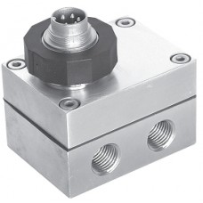
Keller Swiss-Built Series 39X High Accuracy Flow-through Analog Digital Output Wet-Wet Differential Pressure Transmitters
In applications where the differential pressure is more than 5% of the maximum standard pressure range, differential pressure measurement with two absolute pressure sensors offers major advantages over conventional methods of differential pressure measurement (such as the Series PD-10). The Series PD-39 X does not measure the differential pressure directly - instead, it uses two absolute pressure sensors to take the measurement indirectly. As well as reducing costs, this differential pressure transmitter is also more robust in relation to unbalanced (one-sided) overloading. The differential pressure range should be at least 5% of the standard pressure range. Each pressure side has two pressure connections, so the PD-39 X is easy to use in pressure lines. So that the differential pressure can also be measured exactly if the standard pressure range/ differential pressure ratio is high, this series also features the tried-and-tested microprocessorbased technology that is used in Series 30 X. All reproducible pressure sensor errors (i.e. nonlinearities and temperature dependencies) are entirely eliminated thanks to mathematical error compensation. The sensor signals are measured with a 16-bit A/D converter, so the individual standard pressure ranges can be measured to an accuracy of 0,05%FS throughout the entire pressure and temperature range.
Digital Interface The transmitters have a bus-compatible two-wire RS485 half-duplex interface which is modelled on the ”MODBUS RTU”. KELLER offers interface converters to RS232 or USB for use here. The READ30/PROG30 program and the protocol are freely available. The interface offers these capabilities:
- Readout of pressure and temperature values for both sensors. This allows readout of the diffe-
rential pressure as well as the two standard pressure ranges.
- Calibration of zero points and amplification.
- Scaling of the analog output to different pressure ranges or units.
- Configuration settings such as measurement rate, low-pass (LP) filter, bus address, etc.
- Readout of information such as serial number, compensated pressure and temperature ranges, etc.
Analog Output
The analog output is freely scalable via the interface. For flow measurements, the root of the differential pressure can also be outputted. The calculated value can be outputted via an analog interface (0…10 V or 4…20 mA).
Storage-/Operating Temperature -40…100 °C
Compensated Standard Range -10…80 °C
Error Band
(1) (2)
≤ 0,05 %FS typ. ≤ 0,1 %FS max.
True Output Rate 200 Hz
Resolution
(2)
≤ 0,002 %
Long Term Stability typ.
(2)
0,1 %
(1)
Linearity + Hysteresis + Repeatability + Temperature Error
(2)
Accuracy and Resolution referred to Standard Pressure Range
Output Signal 4…20 mA, 2-wire 0…10 V, 3-wire
Supply (U) 8…28 Vcc 13…28 Vcc
Load Resistance (U-7 V) / 0,02 A > 5’000 Ω
Electrical Connection - Binder-plug 723 (5 pole)
- DIN 43650 plug
- MIL C-26482 plug (6 pole)
Programming RS485 half-duplex
Insulation 10 MΩ / 50 V
Pressure Endurance 10 Mio. Pressure Cycles 0...100 %FS at 25 °C
Vibration Endurance 20 g, 20 to 5’000 Hz
Shock Endurance 20 g sinus 11 msec.
Protection IP65
CE-Conformity EN 61000-6-1 to -4 (with screened cable)
Material in Contact with Media Stainless Steel 316L (DIN 1.4435)
Dead Volume Change < 0,1 mm3
Pressure Ports G1/4 female (2 per pressure side)
Weight Series 39 X Low Pressure: ≈ 475 g
Series 39 X Medium Pressure: ≈ 750 g
Options
• Versions for hazardous areas / Other pressure ranges / Supply 32 V / Electrical cable
output / Oil Filling: Fluorized Oil (O2-compatible), Olive Oil, Low Temperature Oil /
Other connections
Double sensor with electronic circuit.
In this state, the sensors are mounted in test
fixtures and tested in furnaces in lots of 100,
subsequently mounted in the Series 39 X Low
Pressure housings.
Polynomial Compensation
This uses a mathematical model to derive the
precise pressure value (P) from the the signals
measured by the pressure sensor (S) and the
temperature sensor (T). The microprocessor in
the transmitter calculates P using the following
polynomial:
With the following coefficients A(T)...D(T) depending on the temperature:
The transmitter is factory-tested at various levels
of pressure and temperature. The corresponding
measured values of S, together with the exact
pressure and temperature values, allow the coef-
ficients A0
...D3
to be calculated. These are written into the EEPROM of the microprocessor.
When the pressure transmitter is in service, the
microprocessor measures the signals (S) and
(T), calculates the coefficients according to the
temperature and produces the exact pressure
value by solving the P(S,T) equation.
Calculations and conversions are performed at
least 200 times per second depending on the
format of the signals.
The resolution is 0,002% of the standard pressure.
Standard Press. Range
Diff. Pressure Range
Max. Error Band of
Stand. Press. Range
x
S
Write a review
Your Name:Your Review: Note: HTML is not translated!
Rating: Bad Good
Enter the code in the box below:


