Buschjost Valves and systems for cleaning dust collectors

Buschjost Valves and systems for cleaning dust collectors
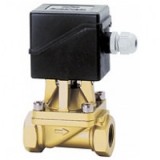
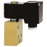
Motorised valve
For neutral gases and liquids
– Interal thread G 1/2 to G 1
– Cartridge system
Operating pressure –0.9 to 10 bar
Description (standard valve)
Motorised valve for e.g. hot water, oil, air
Flow direction:
determined
Fluid temperature:
max.+90 °C
Ambient temperature:
max.+40 °C
Mounting position:
prefer
ably with drive vertical on top ±60°
Material
Body:
Brass (C
W617N)
Seal:
NBR
Control discs:
Oxide-ceramic
Features
•
Low power consumption
•
Choice of compact drives
•
Valve remains on last setting if power lost
•
Will handle contaminated fluids
•
Characteristic data
Valves
Part Number -Wert **
Nominal Diameter Connection size Operatng pressure * k Weight
v
s
1) 3
(motor (Base m
) (mm) min. (bar) max. (bar) /h) (kg)
8288500.96XX ¨ Cartridge ¨C0. 10 1.1 0.7
8288200.96XX 15 G 1/2 ¨C0. 10 1.1 0.9
2)
4.4 1.6
8288300.96XX 20 G 3/4 ¨C0. 6
2)
4.4 1.6
8288400.96XX 20 G 1 ¨C0. 6
1) 2)
See motor drives for motor C
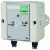
Differenzdruck-Messumformer
Beschreibung (Standardger?t)
Der Differenzdruck-Messumformer ist ein universeller Messumformer f¨1r kleine und mittlere Dr-
cke. Durch die Best¨1ckung mit unterschiedlichen Drucksensoren k?nnen Messbereiche zwischen
2,5 und 100 mbar realisiert werden. Zwei Anschlussleitungen dienen zur Spannungsversorgung.
Der Speisestrom ist das Mess-Signal von 4...20 mA. Der Betriebszustand wird mit einer Leuchtdi-
ode angezeigt.
Technische Daten
Spannungsversorgung: U = 10 - 36 V DC (Hilfsenergie)
b
Messsysteme: Halbleitersensor
Medium: Luft sowie trockene, nicht aggressive Gase
Analogausgang: 4...20 mA (Zweileitertechnik)
Max. zul?ssige B¨1rde R = !Y ( - 9 V) / 0,02 A
A b
Druckanschluss: Push In 6/4
Umgebungstemperatur: ¨C20 !aC ... max. +55
Ausf¨1hrungen
Kunststoffgehuse 88 x 88 x 53 mm
Elektrischer
Anschluss Federkraftklemmen,
max. Anschlussquerschnitt
2
1,0 mm2 feindr?htig, 1,5 mm eindr?htig
Zulassung: Ex tD A22 IP65 T60!a
x II 3D Ex tb IIIB T60!aC D
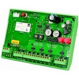
Microcontroller-operated valve controller
Description (standard valve)
The microcontroller-operated valve controller is used for the cycle control of electromagnetic valves
in industrial dust filter systems. The flexible design concept enables the use as PCB version with
spacer sleeves, as standard rail version or as separate control unit in plastic casing with ATEX for
use in Zone 22 approval. To adapt the controller to various valve outputs, it can be equipped with the
corresponding transformer.
Technical Data
Power supply: 230 V AC, 50 - 60 Hz or 24 V DC
Current consumption: 30 VA
Operating temperature: 0 !aC ... +50 !
Valve outputs: 8
Displays:
LED 1 x green "Operation"
1 x yellow "Cleaning"
8 x red assigned to the valves
Control elements:
Start button Set cycles are executed
Test button The next valve is cleaned
Rotary selector
switch Number of valves from 1...8 Cycle setting
Potentiometer Pulse setting, Pause setting
Electrical connection: Cage clamp terminal strips
Valve current: 1 A at a pulse time !Y 1 s and a paus
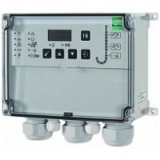
Valve controller for industrial filters
Description (standard valve)
The solenoid valve controller is used for the time- or differential pressure-dependent control of
solenoid valves in industrial dust extraction technology. Up to 64 valves are controlled with the base
unit and three expansion units. The base unit communicates with the expansions over a RS-485
connection. The valves are activated sequentially and are not chamber-oriented. They are monitored
for excess current and interruption. Errors are displayed on the base unit. The controller is simple
to operate through symbol labelling and LEDs for status and differential pressure indications. The
differential pressure signal is supplied as 4...20 mA value. The controller is available purely as time
controller in a version without differential pressure display. Accessories, such as the differential
pressure sensor, the dp-connection set and the valve connector with various line lengths comple-
ment the controller.
Technical Data
Power supply: 230 V AC, 50...60 Hz or 24 V DC
Current consumption: 30 VA
Operating temperature: ¨C20 !aC up to max. +50
Valve outputs: 16 (with expa
Purge Valve
for use with differential pressure regulator Publication 7501550.06.04.96
in dust filter systems Catalogue index
A 20
Description (standard valve)
Solenoid valve for purging measuring lines.
Incorporates electronic pulse control unit.
Flow direction:fixed
Fluid temperature:max+80°,
Ambient temperature:max+55°,
Sum of fluid and
ambient temperature:max+100°,
Mounting position:optional, preferably with
solenoid upright
Materialbody:brass
seat seal:NBR
reinforced fabric diaphragm
Features
B
A
2 2 High flow rate
A B Powerful burst of air
1 1
P Compact design Cleaning time adjustable
Characteristic data
1
Port P:G /4
1
Regulator port:G /8
1
Filter port:G /8
Operating pressure:2 to 8 bar
Differential pressure between
Measuring lines:max 0.2 bar
Pulse duration:0.5 to 10 s
Interval:10 to 120 min
8493571.8803.23050
Cat no:
Solenoid
ETM pulse solenoid cat no: 8803. 23050
Power supply:230 V 50 Hz
Design to:VDE 0580
Protection system to:EN 60529 IP 65
(previous DIN 40 050)
Power consumption:Inrush 50 VA
Holding 24 VA
Available on request Models with different solenoids
Detailed technical data for:ETM pulse soleno
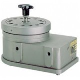
Pneumatic controller
for dust filter valves
for controlling up to 20 filter pulse valves
with ATEX approval
Internal thread P = G 1?8 Z = G 1?4
Operating pressure 2 to 8 bar
Description (standard model)
The device controls a maximum of 20 filter pulse valves and replaces the
solenoid control unit. The pulse valves are connected to the pressure cham-
ber of the controller by small bore airlines.The wiper arm assembly of the
controller is operated by a pneumatic ratchet drive.It pauses between valve
connections for a preset time which is adjustable by the user.The switching
time is also user adjustable by means of a throttle valve accessed after remo-
val of the bottom casing.During the switching time the wiper arm passes be-
neath a valve connection port and vents the pilot line to that particular valve.
The valve opens and remains open until the wiper arm moves on to the next
position. The pilot air is vented through the port marked ?R!° underneath the
manual override knob,which is marked to show the exact position of the wi-
per arm. The control section consists of a pneumatic timer for adjusting the
interval, throttle valve for adjusting the switching tim
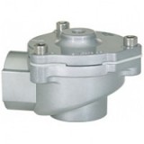
2/2-way valves DN 20 to DN 80
For air
Remote pilot operated
Internal threads G 3/4 up to G 3 or 3/4 NPT up to 3 NPT
Operating pressure 0.4 to 8 bar
Description (standard valve)
Control via separate pilot valve or pilot controller.
Switching function: normally closed
Flow direction: determined
Coil gas temperature: ¨C40 !aC to max. +85
Ambient temperature: ¨C20 !aC to max. +85
Mounting position: optional
Pilot connection: G 1/8 resp. 1/8 NPT
Material
Body: Aluminium
Seat seal: TPE
Features High flow rateClear compact designOne-piece diaphragm
Characteristic Data
Valves
Part Number Nominal Connection Size Valve Length Operating Pressure k -value *
Weight Total
v
3
Diameter (mm) (mm) (Base m
min. max. (bar) /h) (kg)
8290300.0000 G 3/4
20 95.0
0.4 8 18 0.32
8291300.0000 3/4 NPT
8290400.0000 G 1
25 95.0
0.4 8 22 0.29
8291400.0000 1 NPT
8290600.0000 G 1 1/2
40 135.0
0.4 8 59 0.97
8291600.0000 1 1/2 NPT
8290700.0000 G 2
50 170.0
0.4 8 80 1.7
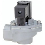
2/2-way valves DN 20 to DN 80
For air
Solenoid pilot operated
Internal threads G 3/4 up to G 3 or 3/4 NPT up to 3 NPT
Operating pressure 0.4 to 8 bar
Description (standard valve)
Switching function: normally closed
t
Flow direction: determined
Coil gas temperature: ¨C40 !aC to max. +85
Ambient temperature: ¨C20 !aC to max. +85
Mounting position: optional, preferably solenoid
vertical on top
Material
Body: Aluminium
Seat seal: TPE
Internal parts: TPU
FeaturesHigh flow rateAll internal components captiveSimple compact designSolenoid interchangeable without toolsIntegrated silencerOne-piece diaphragm
Characteristic Data
Valves
Part Number Nominal Connection Size Valve Length Operating Pressure k -value *
Weight Total
v
3
Diameter (mm) (mm) (Base m
min. max. (bar) /h) (kg)
8296300.8171 G 3/4
20 95.0
0.4 8 18 0.50
8297300.8171 3/4 NPT
8296400.8171 G 1
25 95.0
0.4 8 22 0.47
8297400.8171 1 NPT
8296600.8171 G 1 1/2
40 135.0
0.4 8&nb
2/2-way valves DN 20 to DN 80
For air
Solenoid pilot operated
Internal threads G 3/4 up to G 3 or 3/4 NPT up to 3 NPT
Operating pressure 0.4 to 8 bar
Description (standard valve)
Switching function: normally closed
Flow direction: determined
Coil gas temperature: ¨C40 !aC to max. +85
Ambient temperature: ¨C20 !aC to max. +85
Mounting position: optional, preferably solenoid
vertical on top
Material
Body: Aluminium
Seat seal: TPE
Internal parts: TPU
FeaturesHigh flow rateAll internal components captiveSimple compact designSolenoid interchangeable without toolsIntegrated silencerOne-piece diaphragm
Characteristic Data
Valves
Part Number Nominal Connection Size Valve Length Operating Pressure k -value *
Weight Total
v
3
Diameter (mm) (mm) (Base m
min. max. (bar) /h) (kg)
8296300.8171 G 3/4
20 95.0
0.4 8 18 0.50
8297300.8171 3/4 NPT
8296400.8171 G 1
25 95.0
0.4 8 22 0.47
8297400.8171 1 NPT
8296600.8171 G 1 1/2
40 135.0
0.4 8
2/2-way valves DN 20 to DN 40
For air
Remote pilot operated
Internal threads G 3/4 to G 1 1/2 or 3/4 NPT to 1 1/2 NPT
Operating pressure 0.4 to 8 bar
Description (standard valve)
Controlled by external pilot unit
Switching function: normally closed
Flow direction: determined
Coil gas temperature: ¨C40 !aC to max. +85
Ambient temperature: ¨C20 !aC to max. +85
Mounting position: optional
Control port: G 1/8
Material
Body: Stainless steel (1.4408)
Seat seal: TPE
FeaturesHigh flow rateSimple, compact designOne-piece diaphragm
haracteristic data
Valves
Part Number Nominal Connection size Valve length Operating pressure k -value * Weight
v
3
Diameter (mm) (mm) min. (bar) max. (bar) (Base m /h) (kg)
8330300.0000 G 3/4
20 95 0.4 8 18 0.7
8331300.0000 3/4 NPT
8330400.0000 G 1
25 95 0.4 8 22 0.8
8331400.0000 1 NPT
8330600.0000 G 1 1/2
40 135 0.4 8 59 2.9
8331600.0000 1 1/2 NPT
*Cv-value (US) v kv-value x 1.2
Further options (Valves)
XXXXX54.XXXX Flange version without valve body
XXXXX62.XXXX&nbs
2/2-way valves DN 20 to DN 40
For air
Solenoid pilot operated
Internal threads G 3/4 to G 1 1/2
Operating pressure 0.4 to 8 bar
Description (standard valve)
Switching function: normally closed
Flow direction: determined
t
Coil gas temperature: ¨C40 !aC to max. +85
Ambient temperature: ¨C20 !aC to max. +85
Mounting position: optional, preferably solenoid
vertical on top
Material
Body: Stainless steel (1.4408)
Seat seal: TPE
Internal parts: TPU
FeaturesHigh flow rateAll internal components captiveSimple, compact designSolenoid interchangeable without toolsIntegrated silencerOne-piece diaphragm
Characteristic data
Valves
Part Number Nominal Connection size Valve length Operating pressure k -value * Weight
v
3
Diameter (mm) (mm) min. max. (bar) (Base m /h) (kg)
8332300.8171 20 G 3/4 95 0.4 8 18 0.92
8332400.8171 25 G 1 95 0.4 8 22 1.01
8332600.8171 40 G 1 1/2 135 0.4 8 59 3.11
State voltage [V] and frequency [Hz]
* Cv-value (US) v kv-value x 1.2
Further options (Valves)Solenoid 8171
XXXXX
Microcontroller-operated valve controller
Description (standard valve)
The microcontroller-operated valve controller is used for the cycle control of electromagnetic valves
in industrial dust filter systems. The flexible design concept enables the use as PCB version with
spacer sleeves, as standard rail version or as separate control unit in plastic casing with ATEX for
use in Zone 22 approval. To adapt the controller to various valve outputs, it can be equipped with the
corresponding transformer.
Technical Data
Power supply: 230 V AC, 50 - 60 Hz or 24 V DC
Current consumption: 30 VA
Operating temperature: 0 !aC ... +50 !
Valve outputs: 8
Displays:
LED 1 x green "Operation"
1 x yellow "Cleaning"
8 x red assigned to the valves
Control elements:
Start button Set cycles are executed
Test button The next valve is cleaned
Rotary selector
switch Number of valves from 1...8 Cycle setting
Potentiometer Pulse setting, Pause setting
Electrical connection: Cage clamp terminal strips
Valve current: 1 A at a pulse time !Y 1 s and a paus
2/2-way valves DN 25 to DN 40
For air
Remote pilot operated
Compression Fittings DN 25 and DN 40
Operating pressure 0.4 to 8 bar
Description (standard valve)
Control via separate pilot valve or pilot controller
Switching function: normally closed
Flow direction: determined
Coil gas temperature: ¨C40 !aC to max. +85
Ambient temperature: ¨C20 !aC to max. +85
Mounting position: optional
Pilot connection: G 1/8
Material
Body: Aluminium
Seat seal: TPE
Features High flow rateClear compact designOne-piece diaphragmSimple mounting
Characteristic data
Valves
Part Number Nominal diameter Operating pressure k -value * Weight
v
3
(mm) min. (bar) max. (bar) (Base m /h) (kg)
8364400.0000 25 0.4 8 22 0.7
8364600.0000 40 0.4 8 59 1.85
* Cv-value (US) v kv-value x 1.2
State voltage [V] and frequency [Hz]
Part Number Connection T T1 B H H1 L L1
size (mm) (mm) (mm) (mm) (mm) (mm) (mm)
8364400.0000 34.8 ca. 45 10 80 ca.
2/2-way valves DN 25 to DN 40
For air
Solenoid pilot operated
Compression Fittings DN 25 and DN 40
Operating pressure 0.4 to 8 bar
Description (standard valve)
Switching function: normally closed
Flow direction: determined
Coil gas temperature: ¨C40 !aC to max. +85
Ambient temperature: ¨C20 !aC to max. +85
Mounting position: optional, preferably solenoid
vertical on top
Material
Body: Aluminium
Seat seal: TPE
Internal parts: TPU
Features High flow rateAll internal components captiveSimple compact designSolenoid interchangeable without toolsIntegrated silencerOne-piece diaphragmSimple mounting
Characteristic data
Valves
Part Number Nominal diameter Operating pressure kv-value * Weight
3
(mm) min. max. (bar) (Base m /h) (kg)
8367400.8171 25 0.4 8 22 0.9
8367600.8171 40 0.4 8 59 2.1
State voltage [V] and frequency [Hz]
* Cv-value (US) v kv-value x 1.2
Further options (Valves)Solenoid 8171
XXXXX62.XXXX Crude gas te


