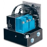
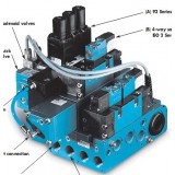
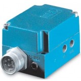
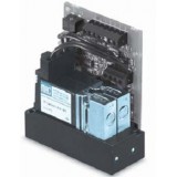
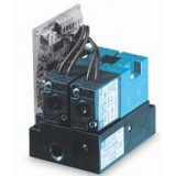
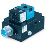
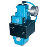
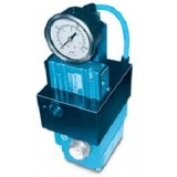
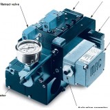
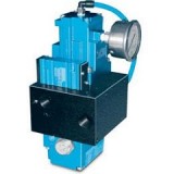
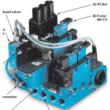
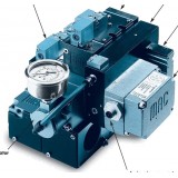
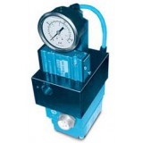
MAC proportional pressure control PQE and pressure control system

| Series | PQE6500 info | PQE92 info |
| Flow Cv | 6.3 | 1.3 |
| Port Size | 1/2-3/4" | 1/4-3/8" |
| Series | Proportional Multi-Pressure Pak info | Multi-Pressure Pak info |
OPERATIONALBENEFITS
1. Reliable operation, using two MAC 35 Series
2. Repeatability.
3. Fast response.
4. Long life.
5. High flow.
6. Low power consumption.
7. Not affected by vibrations.
8. Accurate pressure control.
9. Analog command signal and output.
GENERALDATA
Ambient temperature :32 to 120°,F/0 to 50°
Vibration :Not affected
Port size :1/8°±
Connector :4 pin terminal block
Mounting :Any plane
ELECTRICALDATA
Supply voltage :18 to 28 VDC
Supply current :50 to 350mA
Command signal :4 to 20mA, 0-10v
Command type :Differential
Input impedance :316 °0.1% (current4.99 °1.0% (voltage
EMI/RFI protection :Common mode and high frequency noise reduction
PNEUMATICDATA
Inlet pressure :120 PSI max (for 10-100 PSI output pressure)
8 BAR max (for 0.66-6.6 BAR output pressure)
Fluids :Air or inert gases
Lubrication :Not required, if used select a medium aniline point oil
Output pressure :
0 to 10, 30, 40, 45, 60 and 100
0 to 0.66, 2, 2.6, 3, 4 and 6.6
Overall accuracy :
1.5% full scal
2.5% full scal
Flow :Cv 0.10/100 Nl/min
Minimum closed end volume :1.0 cubic inch
OPERATIONALBENEFITS
1. Fast response.applications.
2. Long life.
3. High flow.
4. The use of a digital command signal brings easy installation and use.
5. A compact and lightweight unit saves room and installation costs.
6. This system is the alternative to proportional valves if more than six pressures or closed loop feedback are not required. is easy to set up and
7. The Multi-Pressure Pakmaintain.
8. For 2, 3 or 4 ported weld guns and other
9. Accuracy of °?2.5 % of full scal
TECHNICALDATA
Min. supply pressure :25 PSI (1.7 BAR)
Max. supply pressure :150 PSI (10 BAR)
Pressure output range :25-120 PSI (1.7 to 8 BAR)
Voltages available AC :120/60, 110/50
DC :12 & 24 volt. 1.8 to 12.7 watts
Other AC and DC
Consult factory
voltages available :
Air supply :40 micron filtration
Lubrication :Not required but if lubrication is used, a medium aniline point oil is recommended
NOTE: Pressures shown are minimum and maximum safe working pressures.
*Series Port size Flow
82 1/4" - 3/8" C 0.9 / 900 Nl/Min
v
93 3/8" - 1/2" C 2.4 / 2400 Nl/Min
v
6300 3/8" - 1/2" C 2.1 / 2100 Nl/Min
v
6500 1/2" - 3/4" C 3.5 / 3500 Nl/Min
v
ISO 1 1/4" - 3/8
AMS ¨C NALOG MONITOR SIGNAL
- 0-10 VDC FEEDBACKSIGNALTHATPROVIDESAVOLTAGE
PROPORTIONALTOTHEOUTPUTPRESSURE
LMS 1 ¨C OGIC MONITOR SIGNAL
- 5 VDC (TTL HIGH), 24 VDC (HIGH), 5 VDC (LOW),OR 24 VDC (LOW)
!
GO/ NOGO! FEEDBACKSIGNAL (DEPENDINGONREQUIREMENTS)
LMS 2 ¨C
OGIC MONITOR SIGNAL
- 5 VDC (TTL LOW), 24 VDC (HIGH),OR 24 VDC (LOW) !GO / NOGO
FEEDBACKSIGNAL
(DEPENDINGONREQUIREMENTS)
CV+ - P
OSITIVE COMMAND SIGNAL
- POSITIVELEADFORTHE 0 ¨C 10 VDCOR 4-20MACOMMANDSIGNAL
(DEPENDSONREQUIREMENTS)
CV- - N
EGATIVE COMMAND SIGNAL
- NEGATIVELEADFORTHE 0 ¨C 10 VDCOR 4 ¨C20MACOMMANDSIGNAL
(DEPENDSONREQUIREMENTS)
C
OM ¨C AIN POWER COMMON
- COMMONLEADFORTHE 24 VDC POWER
PWR ¨C AIN POWER
- POSITIVE LEADFORTHE 24 VDC POWER
OPERATIONALBENEFITS
1. Reliable operation, using two MAC 34 Series
with balanced poppet.
2. Fast response.
3. Long life.
4. High flow.
5. Low power consumption.
6. Not affected by vibrations.
7. Accurate pressure control.
8. Analog command signal and output.
GENERALDATA
Ambient temperature :32 to 120°,F/0 to 50°
LED indicators :Red : power on - Green : pressure achieved
Vibration :Not affected
Port size :G 1/8°±, 1/8°± NPT - Option : bottom por
Connector :7 pin terminal block
Mounting :Any plane
ELECTRICALDATA
Supply voltage :20.4 to 26.4 VDC
Supply current :50 to 275mA
Command signal :0 to 10V or 4 to 20mA
Command type :Single-ended or differential
Input impedance :4.99 k °1.0% (voltage316 °?0.1% (current
Analog Monitor Signal (AMS) :0 to 10 Volt
Logic Monitor Signal (LMS) :2 types of signals (see How to order) (sinking)
EMI/RFI protection :Common mode and high frequency noise reduction for electrical inputs
PNEUMATICDATA
Inlet pressure* :
120 PSI max (for 10-100 PSI output pres.)
8 BAR max (for 0.66-6.6 BAR output pres.)
Fluids :Compressed air or inert gases
Lubrication :Not required. However, if used, a medium aniline point oil is
OPERATIONALBENEFITS
1. Reliable operation, using two MAC 45 Series
with balanced poppet.
2. Fast response.
3. Long life.
4. High flow.
5. Low power consumption.
6. Not affected by vibrations.
7. Accurate pressure control.
8. Analog command signal and output.
GENERALDATA
Ambient temperature :32 to 120F/0 to 50
LED indicators :Red : power on - Green : pressure achieved
Vibration :Not affected
Port size :G 1/8±, 1/8± NPT - Option : bottom por
Connector :7 pin terminal block
Mounting :Any plane
ELECTRICALDATA
Supply voltage :20.4 to 26.4 VDC
Supply current :50 to 350mA
Command signal :0 to 10V or 4 to 20mA
Command type :Single-ended or differential
Input impedance :4.99 k 1.0% (voltage316 0.1% (current
Analog Monitor Signal (AMS) :0 to 10 Volt
Logic Monitor Signal (LMS) :2 types of signals (see How to order) (sinking)
EMI/RFI protection :Common mode and high frequency noise reduction for electrical inputs
PNEUMATICDATA
Inlet pressure* :
120 PSI max (for 10-100 PSI output pres.)
8 BAR max (for 0.66-6.6 BAR output pres.)
Fluids :Compressed air or inert gases
Lubrication :Not required. However, if used, a medium aniline point oilis recommended
O
OPERATIONALBENEFITS
1. Reliable operation, using two MAC 45 Series
with balanced poppet.
2. Fast response.
3. Long life.
4. High flow.
5. Low power consumption.
6. Not affected by vibrations.
7. Accurate pressure control.
8. Analog command signal and output.
GENERALDATA
Ambient temperature :32 to 120F/0 to 50
LED indicators :Red : power on - Green : pressure achieved
Enclosure :Aluminium Barstock, sealed
Vibration :Not affected
Port size :1/8± (side only
Connector :3, 5, 6 or 7 Pin Plug-in or 7 wire grommet
Mounting :Any plane
Washdown :Standard
ELECTRICALDATA
Supply voltage :20.4 to 26.4 VDC
Supply current :50 to 350mA
Command signal :0 to 10V or 4 to 20mA
Command type :Single-ended or differential
Input impedance :4.99 k 1.0% (voltage 316 0.1% (current
Analog Monitor Signal (AMS) :0 to 10 Volt
Logic Monitor Signal (LMS) :2 types of signals (see How to order) (sinking)
EMI/RFI protection :Common mode and high frequency noise reduction for electrical inputs
PNEUMATICDATA
Inlet pressure* :120 PSI max (for 10-100 PSI output pres.),8 BAR max (for 0.66-6.6 BAR output pres.)
Fluids :Compressed air or inert gases
Lubrication :Not required. Howev
OPERATIONALBENEFITS
1. Reliable operation, using two MAC 34 Series
with balanced poppet.
2. Fast response.
3. Long life.
4. High flow.
5. Low power consumption.
6. Rugged enclosure.
7. Not affected by vibrations.
8. Accurate pressure control.
9. Can be stand alone or used in combination
with our remote air sandwich regulators.
10. Analog command signal and output.
GENERALDATA
Ambient temperature :32°,F to 120°,F/0 to 50
LED indicators :Red : power on - Green : pressure achieved
Enclosure :Aluminium, sealed
Vibration :Not affected
Port size :G 1/8°±, 1/8°± NPT - Option : bottom por Micro or mini 3, 5 or 6 pin plug-in
Connector :3, 4, 5 or 6 wire grommet
Mounting :Any plane
Protection :IP 65
ELECTRICALDATA
Supply voltage :20.4 to 26.4 VDC
Supply current :50 to 275mA (single transducer), 50 to 500mA (dual transducer)
Command signal :0 to 10V or 4 to 20mA
Command type :Single-ended or differential
Input impedance :4.99 k °1.0% (voltage, 316 °?0.1% (current
Analog Monitor Signal (AMS) :0 to 10 Volts
Logic Monitor Signal (LMS) :TTL or 24V 10mA max. (sinking)
EMI/RFI protection :Common mode and high frequency noise reduction for electrical inputs
1 Type
A Analog
2 Mounting / Port Size & Type
AA Base Side Port 1/8!± NPT
AB Base Side Port 1/8!± BSPP
AC Base Side Port 1/8!± BSPT
AD Base Side 10/32
AE Base Side Port M5
AF Base Side M4 Tube Receptacle
AG Base Side 5/32 Tube Receptacle
CA* Base Manifold Mt.
DA DIN Rail Base 1/8!± NPTF Side Por
DB DIN Rail Base 1/8!± BSPPL Side Por
DC DIN Rail Base 1/8!± BSPTR Side Por
DD DIN Rail Base 10/32 Side Port
DE DIN Rail Base M5 Side Port
DF DIN Rail Base M4 Tube Receptacle
DG DIN Rail Base 5/32 Tube Receptacle
3 Pressure Range
0A 100 psi
0B 60 psi
0C 30 psi
0D 15 psi
0N 10 psi
0T 45 psi
0J 75psi
0L 4 psi
4 Pressure Reference
G Gage Pressure
5 Accuracy
A !à 1.5% F.S
C !à 0.5% F.S
E !à 2.5% F.S
6 Command Signal
B 0 - 10v Differential
D 4 - 20mA Differential
7 LMS Signal
A TTL LMS & AMS
8 Cover
A No Cover
1 Spacing
00 29.00mm Spacing
A Side Cylinder Ports
3 Style
A Standard
4 Port Size and Thread Type
A 1/8!± NPT
B 1
OPERATIONOFTHEPQE
1. The pilot operated regulator and the PPC5C are both fed from a common inlet.
2. The °∞out°± port of the PPC5C sends pressure to the pilot port of the pilot operated regulator and to the °∞12°±
of the 400 Series Quick Exhaust Valve. The secondary pressure of the pilot operated regulator is sent to the
output port of the block and it is also sent to the °∞14°± end and inlet of the 400 Series Quick Exhaust Valv
3. The outlet pressure of the PPC5C along with the memory spring in the 400 Series valve will keep the valve in a
closed state as the unit increases pressure.
4. To reduce pressure, drop the PPC5C°Os signal. This will lower the pressure on the °∞12°± end of the 400 Ser
valve. The °∞14°± end of the 400 Series valve now has higher pressure causing a snap-action shifting of the 4
Series valve which will quickly exhaust the downstream pressure to the new selected pressure.
PNEUMATICDATA
Inlet pressure :120 PSI max
Fluids :Air or inert gases
Lubrication :Not required. However, if used, a medium aniline point oilis recommended
Filtration :40 micron
*Output pressure :20 to 100 PSI
Overall accuracy :2.5% full scale
All ports :1/2, 3/4, NPTF, BSPP
OPERATIONOFTHEPQE
1. The pilot operated regulator and the PPC5C are both fed from a common inlet.
2. The °∞out°± port of the PPC5C sends pressure to the pilot port of the pilot operated regulator and to the °∞12°±
of the 400 Series Quick Exhaust Valve. The secondary pressure of the pilot operated regulator is sent to the
output port of the block and it is also sent to the °∞14°± end and inlet of the 400 Series Quick Exhaust Valv
3. The outlet pressure of the PPC5C along with the memory spring in the 400 Series valve will keep the valve in a
closed state as the unit increases pressure.
4. To reduce pressure, drop the PPC5C°Os signal. This will lower the pressure on the °∞12°± end of the 400 Ser
valve. The °∞14°± end of the 400 Series valve now has higher pressure causing a snap-action shifting of the 4
Series valve which will quickly exhaust the downstream pressure to the new selected pressure.
OPERATIONALBENEFITS
1. Accurate pressure control.
2. Fast response.
3. High flow.
4. Quick exhaust function.
5. Unaffected by change in line pressure.
6. Long life.
7. Designed to meet Nema 4 specifications.
8. Analog control.
9. Analog or TTL feedback.
10. Closed loop s
OPERATIONALBENEFITS
1. Fast response. 8. For 2, 3 or 4 ported weld guns and other
2. Long life. applications.
3. High flow. 9. Accuracy of °?2.5 % of full scale (consult factor
4. The use of an analog or 4 bit or 8 bit command for other accuracies).
signal brings increased accuracy in pressure 10. DeviceNet compatible.
control.
5. A compact unit saves room and installation
costs.
6. The analog and logic (TTL) outputs allow
for constant pressure monitoring from
the control unit.
7. Infinite or discrete number of pressures
available.
TECHNICALDATA
Supply pressure :
2 to 10 bar/30 to 150 PSI
*Output pressure :
Standard : 1.7 to 10 bar, other ranges upon request.
25 to 150 PSI
* For 82 and ISO 1 - 1.7 to 8 BAR, 25 to 120 PSI
*Series Port size Flow
82 1/4" - 3/8" C 0.9 / 900 Nl/Min
v
93 3/8" - 1/2" C 2.4 / 2400 Nl/Min
v
6300 3/8" - 1/2" C 2.1 / 2100 Nl/Min
v
6500 1/2" - 3/4" C 3.5 / 3500 Nl/Min
v
ISO 1 1/4" - 3/8" C 1.1 / 1100 Nl/Min
v
ISO 2 3/8" - 1/2" C 2.1 / 2100 Nl/Min
v
ISO 3 1/2" - 3/4" C 5.0 / 5000 Nl/Min
v
OPERATIONALBENEFITS
1. Accurate pressure control.
2. Fast response.
3. High flow.
4. Quick exhaust function.
5. Unaffected by change in line pressure.
6. Long life.
7. Designed to meet Nema 4 specifications.
8. Analog control.
9. Analog or TTL feedback.
10. Closed loop system.
PPCTYPE
Analog, single transducer external sense, bottom O-ring mount
ELECTRICALDATA
Reference PPC5Cspecifications
PHYSICALDATA
Connector :Reference PPC5Cspecifications
Enclosure :Aluminum, sealed
Mounting :Any plane
Ambient temperature range :0 to 50C (32F to 120
PNEUMATICDATA
Inlet pressure :120 PSI max
Fluids :Air or inert gases
Lubrication :Not required. However, if used, a medium aniline point oil is recommended
Filtration :40 micron
*Output pressure :20 to 100 PSI
Overall accuracy :2.5% full scale
All ports :1/2, 3/4, NPTF, BSPPL, BSPTR
Flows :
Output flow :
1/2± ports: Cv 5.33/4± ports: Cv 6
Exhaust flow :
1/2± ports: Cv 1.53/4± ports: Cv 1
**Output volume requirements :Port sizeOutput volume atMinimum length end of output pipeof output pipe 1/2±100 Cu. in. and larger78 50 to 99 Cu. in.100 3/4±100 Cu. in. and larger60 50 to 99 Cu. in.90
* The quick exhaust portion
OPERATIONALBENEFITS
1. Fast response.
applications.
2. Long life.
3. High flow.
4. The use of a digital command signal brings
easy installation and use.
5. A compact and lightweight unit saves room
and installation costs.
6. This system is the alternative to proportional
valves if more than six pressures or closed
loop feedback are not required.
7. The Multi-Pressure Pak
is easy to set up and
maintain.
8. For 2, 3 or 4 ported weld guns and other
9. Accuracy of 2.5 % of full scal
TECHNICALDATA
Min. supply pressure :
25 PSI (1.7 BAR)
Max. supply pressure :
150 PSI (10 BAR)
Pressure output range :
25-120 PSI (1.7 to 8 BAR)
Voltages available AC :
120/60, 110/50
DC :
12 & 24 volt. 1.8 to 12.7 watts
Other AC and DC
Consult factory
voltages available :
Air supply :
40 micron filtration
Lubrication :
Not required but if lubrication is used, a medium aniline point oil is recommended
NOTE: Pressures shown are minimum and maximum safe working pressures.
*Series Port size Flow
82 1/4" - 3/8" C 0.9 / 900 Nl/Min
v
93 3/8" - 1/2" C 2.4 / 2400 Nl/Min
v
6300 3/8" - 1/2" C 2.1 / 2100 Nl/Min
v
6500 1/2" - 3/4" C 3.5 / 3500 Nl/Min
OPERATIONALBENEFITS
1. Fast response.
2. Long life.
applications.
3. High flow.
4. The use of an analog or 4 bit or 8 bit command
for other accuracies).
signal brings increased accuracy in pressure
10. DeviceNet compatible.
control.
5. A compact unit saves room and installation
costs.
6. The analog and logic (TTL) outputs allow
for constant pressure monitoring from
the control unit.
7. Infinite or discrete number of pressures
available.
8. For 2, 3 or 4 ported weld guns and other
9. Accuracy of 2.5 % of full scale (consult factor
TECHNICALDATA
Supply pressure :
2 to 10 bar/30 to 150 PSI
*Output pressure :
Standard : 1.7 to 10 bar, other ranges upon request.
25 to 150 PSI
* For 82 and ISO 1 - 1.7 to 8 BAR, 25 to 120 PSI
*Series Port size Flow
82 1/4" - 3/8" C 0.9 / 900 Nl/Min
v
93 3/8" - 1/2" C 2.4 / 2400 Nl/Min
v
6300 3/8" - 1/2" C 2.1 / 2100 Nl/Min
v
6500 1/2" - 3/4" C 3.5 / 3500 Nl/Min
v
ISO 1 1/4" - 3/8" C 1.1 / 1100 Nl/Min
v
ISO 2 3/8" - 1/2" C 2.1 / 2100 Nl/Min
v
ISO 3 1/2" - 3/4" C 5.0 / 5000 Nl/Min
v
OPERATIONALBENEFITS
1. Accurate pressure control.
2. Fast response.
3. High flow.
4. Quick exhaust function.
5. Unaffected by change in line pressure.
6. Long life.
7. Designed to meet Nema 4 specifications.
8. Analog control.
9. Analog or TTL feedback.
10. Closed loop system.
PPCTYPE
Analog, single transducer external sense, bottom O-ring mount
ELECTRICALDATA
Reference PPC5Cspecifications
PHYSICALDATA
Connector :Reference PPC5Cspecifications
Enclosure :Aluminum, sealed
Mounting :Any plane
Ambient temperature range :0 to 50C (32F to 120
PNEUMATICDATA
Inlet pressure :120 PSI max
Fluids :Air or inert gases
Lubrication :Not required. However, if used, a medium aniline point oil is recommended
Filtration :40 micron
*Output pressure :20 to 100 PSI
Overall accuracy :2.5% full scale
All ports :1/4, 3/8, NPTF, BSPPL, BSPTR
Flows :Output flow :1/4± ports: Cv 0.943/8± ports: Cv 1
Exhaust flow :1/4± ports: Cv 1.33/8± ports: Cv 1
**Output volume requirements :Port sizeOutput volume atMinimum length end of output pipeof output pipe 1/4±100 Cu. in. and larger12 50 to 99 Cu. in.50 3/8±100 Cu. in. and larger 24 50 to 99 Cu. in.50
* The quick exhaust portion of th


