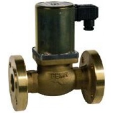
Honeywell Solenoid valves for gas, liquid gas/fuel K-series Flange connection K15G31F
Suitable for all gases in accordance with DVGW, Worksheet G 260, for liquid gas in the liquid phase (up to DN 25 inclusive) and for fuel oil.
No minimum differential pressure required. For explosion-endangered areas (zone 1, 2 and 21, 22) solenoid actuators with pressure-proof
encapsulated solenoid systems ( II G/D Eex de IIC T4 IP65 T125°C) are available. Reg. no.: PTB 04 ATEX 1026
DN size mm 15
Kvs value 4
Static pressure PN40
Working range 0...25
Connections Flange
Class B
Technical data
Type: 2/2-way
Operating mode: normally closed
Type of construction: Piston-type solenoid valve, coupled, no minimum differential pressure required. Valve class to DIN EN 161 B for DN 15 – DN 32,C for DN 40 – DN 50
Materials: Casing: Bronze Rg 5 to DIN 1705, Internal parts: Brass (CuZn40Pb) and corrosion-resistant steel
Sealing materials: Piston: Perbunan (NBR).
Nozzle: Perbunan (NBR).
Static seal: Perbunan (NBR).
Mounting position: Standard version: Solenoid system upright, Ex-version: Solenoid system upright. Other mounting positions not permitted.
Outdoor installations
Standard version: fr = suitable for outdoor use Ex-version: Can be used with upright solenoid system in outdoor installations (see technical notes on Ex solenoid actuators).
Ambient temperature: -15°C to +60°C
Temperature of medium: -15°C to +60°C
Working pressure: See Product Summary
Flanges
To DIN 2501 Part 1, PN 40 for DN 15–32, PN 25 for DN 40/50
Recommended weld-on flanges, PN 40 to DIN 2635
Maintenance:
The valve should be operated 5-10 times per month to prevent the piston from
sticking. No further maintenance is required.
Operating mode: normally closed
DN size Kvs value Working range Connections Registrations Valve class Type
mm bar
15 4.0 0–4 G 1/2“ 1, 5 B K15G31M
20 4.8 0–4 G 3/4“ 1, 5 B K20G31M
15 4.0 0–25 1, 2, 4, 5, 6 B K15G31F
20 4.8 0–25 1, 2, 4, 5, 6 B K20G31F
25 10 0–25 Flange 1, 2, 4, 5, 6 B K25G31F
32 13 0–25 1, 2, 4, 5, 6 B K32G31F
40 34 0–20 1, 2, 4, 5, 6 C K40G31F
50 40 0–20 1, 2, 4, 5, 6 C K50G31F
Ex-versions
15 4.0 0–4 G 1/2“ 1, 5 B K15G35M-Ex
20 4.8 0–4 G 3/4“ 1, 5 B K20G35M-Ex
15 4.0 0–25 1, 2, 4, 5, 6 B K15G35F-Ex
20 4.8 0–25 1, 2, 4, 5, 6 B K20G35F-Ex
25 10 0–25 Flange 1, 2, 4, 5, 6 B K25G35F-Ex
32 13 0–25 1, 2, 4, 5, 6 B K32G35F-Ex
40 34 0–20 1, 2, 4, 5, 6 C K40G35F-Ex
50 40 0–20 1, 2, 4, 5, 6 C K50G35F-EX
Write a review
Your Name:Your Review: Note: HTML is not translated!
Rating: Bad Good
Enter the code in the box below:


