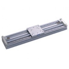
Koganei cylinder side slide Magnet Type Rodless Cylinder MRW Series
・Highly rigid type with two linear guides.
・Shock absorber units are standard equipment.
・Direct mounting at the end plate and mounting the T slots on the bottom improves the mounting flexibility.
| Bore mm | Stroke mm | Port |
| 16-40 | 100-1000 | M5.Rc1/8 Rc1/4 |
Sensor switch
Blank : No sensor switch
ZE135 : 2-lead wire Solid state typewith indicator lampDC1028V
ZE155 : 3-lead wire Solid state typewith indicator lampDC4.528V
ZE101 : 2-lead wire Reed switch typewithout indicator lampDC528V, AC85115V
ZE102 : 2-lead wire Reed switch typewith indicator lampDC1028V, AC85115V
Heli-sert and locating dowel pin hole on the table
Blank : No heli-sert and dowel pin hole
P : With heli-sert and dowel pin hole
Shock absorber (Standard equipment)
KL : Impact speed1001000mm/s [3.939.4in./sec.]
KM : Impact speed1002000mm/s [3.978.7in./sec.]
Code
Model
(for 16 [0.630in.])
KSHJ10 10-01,KSHJ10 10-02
(for 25 [0.984in.])
KSHJ14 12-01,KSHJ14 12-02
(for 40 [1.575in.])
KSHJ20 16-01,KSHJ20 16-02
Solid state type (ZE135, ZE155)
C
B
14 [0.551]
178 [3.071]
ORW16, MRW16
198 [3.858] 174.5 [2.933]
19 [0.748]
100 [3.937]
ORW25, MRW25
125 [4.921] 196.5 [3.799]
22 [0.866]
137 [5.394]
ORW40, MRW40
165 [6.496] 133.5 [5.256]Reed switch type (ZE101, ZE102)
D
C
174 [2.913]
171.5 [2.815]
14 [0.551]ORW16, MRW16
98 [3.858]
196 [3.780]
193.5 [3.681]
19 [0.748]ORW25, MRW25
125 [4.921]
133 [5.236]
130.5 [5.138]
22 [0.866]ORW40, MRW40
165 [6.496]
SLIT TYPE RODLESS CYLINDERSEquivalent bore size:16,25, 40
[0.630in.][0.984in.][1.575in.]
MAGNET TYPE RODLESS CYLINDERSBore size:16,25, 40
[0.630in.][0.984in.][1.575in.]
Pitching (Mp)
High rigidity
Yawing (My)Pitching moment:
(ORW40 MRW40)
,
N m [136ft lbf]
185Rolling moment:
(ORW40 MRW40)
,
N m [148ft lbf]
200Yawing moment:
(ORW40 MRW40)
,
N m [136ft lbf]
185
Remark: Rodless cylinders ORS and MRS series:Pitching moment:60Nm [44ftlbf] (ORS40, MRS40)
Rolling (Mr)Rolling moment:50Nm [37ftlbf] (ORS40, MRS40)Yawing moment:60Nm[44ftlbf] (ORS40, MRS40)
Shock absorber units are standard equipment.
Uses embedded type sensor switch
Specified stroke 10mm [0.394in.]
Since the shock absorber can be used for
fine stroke adjustment of 5mm [0.197in.]
for one side, it totally offers a 10mm
[0.394in.] margin in regards to the
specified stroke.
Piping concentrated on one side
Since shock absorber unit provides position-Concentrated connection ports as standard
ing of the end of the stroke, it enhancesequipment save space.
Easily and clearly pulling out lead wires from
absorbing capacity to the maximum extent.
the grooves on the body.
The shock absorber does not protrude
beyond the end plate. Moreover, moving the
shock absorber unit is all that is required to
adjust the stroke all along its range.
Note
Model
Guide model
ORW16, MRW16
LWL12
ORW25, MRW25
LWL15
ORW40, MRW40
LWES15
Moment and
Max. load
Model
ORW16, MRW16
ORW25, MRW25
ORW40, MRW40
Specifications
Equivalent bore size mm [in.]
16 [0.630] 25 [0.984] 40 [1.575]
Item
Note 1
Media
Air
Operation type
Double acting type
Operating pressure rangeMPa [psi.]
0.150.8 [22116]
Proof pressureMPa [psi.]
1.2 [174]
Operating temperature range°,C [°,
060 [32140]
Note 2 Note 2 Note 2
Operating speed rangemm/s [in./sec.]
1501000 [5.939.4] (1502000 [5.978.7]) 1001000 [3.939.4] (1002000 [3.978.7]) 1001000 [3.939.4] (1001500 [3.959.1])
Cushion
Shock absorber (Standard equipment on both ends)
Cylinder portion
Not required (If lubrication is required, use Turbine Oil Class 1 [ISO VG32] or equivalent.)
Lubrication
Guide portion
Required (Lithium soap-based grease)
Repeatability mm [in.]0.05 [0.002]
Note 3
mm [in.]
Parallelism
0.3 [0.012]
Attachment holder mm [in.]
Stroke
Adjustable over the entire stroke
Shock absorber mm [in.]
Adjusting range
Fine adjustmentOne side(R)C5 [(R)C0.190.197]
Maximum stroke mm
2000
Note 4
Maximum load capacity N [lbf.]
130 [29] 300 [67] 600 [135]
Port size
M50.8 Rc1/8 Rc1/4
Notes:1.Use clean air that contains no moisture, dust, oxidized oil or the impurities in the compressed air.
2.Figures in parentheses ( ) are for when ORW series with shock absorbers are set for 2000mm/s [78.7in./sec.] impact speed.
3.This is the parallelism between the upper surface of the table and the bottom of the body. It is not the same as the traveling parallelism.
4.For the relation between the mass and piston speed, see the shock absorber absorption capacity graph on p.1205.![]()
Write a review
Your Name:Your Review: Note: HTML is not translated!
Rating: Bad Good
Enter the code in the box below:


