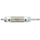
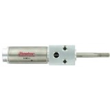
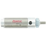
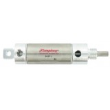
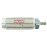
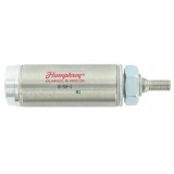
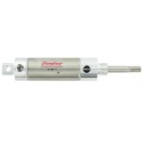
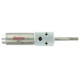
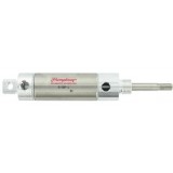
Humphrey Air Cylinder

• Air pressure produces equal force in both directions
due to equal piston area; permits “locking” in midstroke
• One rod can be used to perform a work function,
second rod to operate limit switches, provide support
or guide
• Fixed mounting of both rod ends allows movement
of barrel only
• Bumpers and Stainless Steel Rod, standard
• Options: E, F, J, K, L, M, P, W
• Two mounting nuts included, except Model 3 & 4; order separately.
*See Accessories section.
BASIC
Piston Area SQ. IN.†
MODEL Volume CU. IN.
NO. (per inch of stroke)
8 .17
7 .39
6 .81
25 1.08
5 1.62
75 2.21
4 2.84
3 4.60
†Area x PSIG = Approximate Force
Medium . . . . . . . . . . . . . . . . . . Compressed Air
Pressure range. . . . . . . . . . . . . . . . 0–200 PSIG
Temperature range . . . . . . . . . . . . . . . –40°F to
160°F Ambient*
w/Fluoroelastomer . . . . . . . –20°F to 400°F
Ambient*
Recommended maximum stroke . . . . . . . . .129
*Additional heat may be generated by
seal friction (high speed cycling)
N
X
MODEL B D E F J K L M MM Add to P Q R Pilot
& BORE Dia. Rod Nose Wrench Rod Thread Nose Port Length Length For e
• Versatile mounting...
through-head, or front mount
using pilot
• Stainless Steel Rod, standard
• Wearstrip standard (Double
acting only): 5 inches or more of
stroke (Optional, shorter strokes)
• Options: A, B, E, F, J, K, L, M, N, P
*Order separately. See Accessories section.
Medium. . . . . . . . . . . . . . . . . . . . Compressed Air
Pressure range . . . . . . . . . . . . . . . . . 0–200 PSIG
Temperature range . . . . . . . . . . . . . . . . . –40°F to
160°F Ambient*
w/Fluoroelastomer . . . . . . . . . –20°F to 400°F
Ambient*
*Additional heat may be generated by
seal friction (high speed cycling)
Piston Area SQ. IN.†
Volume CU. IN.
BASIC (per inch of stroke)
MODEL Plain Side Rod Side
8-BFD .20 .17
7-BFD .44 .39
6-BFD .89 .81
5-BFD 1.77 1.62
MODEL B D F G H J K L M P Q R T Pilot Y Z
& BORE Square Rod Wrench Flat Flat Rod Thread Mounting Holes Port Length For each Pilot Rod Dia. Mounting
TYPE Exten. Flat x Length (NPSF) stoke Add to Dia. – .001 Through Holes
(Stroke) increment M – .006
of
Two #8-32 holes
8-BFD-h 1
/2 .75 .50 None .12 .37 10-32 x .50 on .75 diameter
10-32
2.62
1
/29 .50 .31 .06 .18
Stainless Steel Rod, standard
• Simple, reliable design
• Requires air presure to extend and retract rod
• Extend force exceeds retract force (smaller effective
are on rod side of piston)
• Exclusive Humphrey Reversible Piston
• Specify Option M (Internal Magnet) to operate
sensors
• Wearstrip standard: 5 inches or more of stroke
(optional, shorter strokes N/A on model 8)
• Options: A, B, E, F, J, K, L, M, N, P, W
Mounting Nut included, except Model 4 & 3; order separately.
*See Accessories section.
Piston Area SQ. IN.†
Volume CU. IN.
BASIC (per inch of stroke)
MODEL Rod
NO. Plain Side Side
8 .20 .17
7 .44 .39
6 .89 .81
25 1.23 1.08
5 1.77 1.62
75 2.41 2.21
4 3.14 2.84
3 4.91 4.60
†Area x PSIG = Approximate Force
Medium. . . . . . . . . . . . . . . . . . . . Compressed Air
Pressure range . . . . . . . . . . . . . . . . . 0–200 PSIG
Temperature range . . . . . . . . . . . . . . . . . –40°F to
160°F Ambient*
w/Fluoroelastomer . . . . . . . . . –20°F to 400°F
Ambient*
Recommended maximum stroke. . . . . . . . . . .129
*Additional heat may be generated by
seal friction (high speed cycling)
N
Options: B, E, F, J, K, L, M, N, P, R, T, W, U.
• Versatile mounting, Pivot, Nose, Double-End
*See Accessories section.
Piston Area SQ. IN.†
Volume CU. IN.
BASIC (per inch of stroke)
MODEL Rod
NO. Plain Side Side
8 .20 .17
7 .44 .39
6 .89 .81
25 1.23 1.08
5 1.77 1.62
75 2.41 2.21
4 3.14 2.84
3 4.91 4.60
†Area x PSIG = Approximate Force
Medium. . . . . . . . . . . . . . . . . . . . Compressed Air
Pressure range . . . . . . . . . . . . . . . . . 0–200 PSIG
Temperature range . . . . . . . . . . . . . . . . . –40°F to
160°F Ambient*
w/Fluoroelastomer . . . . . . . . . –20°F to 400°F
Ambient*
Recommended maximum stroke. . . . . . . . . . .129
*Additional heat may be generated by
seal friction (high speed cycling)
N
X
MODEL B D E F J K L M MM P Q R T U V Pilot Z
& BORE Dia. Rod Nose Wrench Rod Thread Nose Port Length Length For each Pilot Rod Dia. Pivot
TYPE Exten. Length Flat x Length & Pivot (NPSF) stoke Add to Dia. – .001 Hole
(Stroke) Thread increment MM – .006 Dia.
of:
8-DP-h 1
/2 .62 .50 .41 None 10-32 x .50
7
/16-20
10-32
3.31* 3.06*
1
/29 .50 .37 .04 .187 .42 .25 .31 .437 .
HUMPHREY AIR CYLINDERS
• Stainless Steel Rod, standard
• Economical—requires air pressure only to extend rod
• Stress relieved spring/s retract rod
• Options: A, B, E, F, and P
*Mounting nut included, except Model 4; order separately.
*See Accessories section.
Medium. . . . . . . . . . . . . . . . . . . . Compressed Air
Pressure range . . . . . . . . . . . . . . . . . 0–200 PSIG
Temperature range . . . . . . . . . . . . . . . . . –40°F to
160°F Ambient*
w/Fluoroelastomer . . . . . . . . . –20°F to 400°F
Ambient*
Recommended maximum stroke . . . . . . . . . . .69
*Additional heat may be generated by
seal friction (high speed cycling)
BASIC
Piston Area SQ. IN.† Spring Tension
MODEL Volume CU. IN.
Pounds
NO. (per inch of stroke) Free Comp.
8 .20 1 2
7 .44 1.5 5
6 .89 4 8
25 1.23 7 14
5 1.77 6 12
75 2.41 12 24
4 3.14 15 30
†Area x PSIG = Approximate Force
N
X
MODEL B D E F G H J K L M Q R Pilot
& BORE Dia. Rod Nose Wrench Flat Flat Rod Thread Nose Port Length For each Pilot Rod Dia.
TYPE Exten. Length Flat x Length Thread (NPSF) stoke Add to Dia. – .001
(Stroke) increment M – .006
of:
8-S-
1
Spring Tension
MODEL Volume CU. IN.
Pounds
NO. (per inch of stroke) Free Comp.
8-BFS .20 1 2
7-BFS .44 1.5 5
6-BFS .89 4 8
5-BFS 1.77 6 12
8-BFSR .17 1 4
7-BFSR .39 1.5 7.5
6-BFSR .81 4 12
5-BFSR 1.62 6 18
†Area x PSIG = Approximate Force
Medium. . . . . . . . . . . . . . Compressed Air
Pressure range . . . . . . . . . . . 0–200 PSIG
Temperature range . . . . . . . . . . . –40°F to
160°F Ambient*
w/Fluoroelastomer . . . –20°F to 400°F
Ambient*
*Additional heat may be generated by
seal friction (high speed cycling)
BFS Single Acting
N
X
MODEL B D F G H J K L M P Q R T Pilot Y Z
& BORE Square Rod Wrench Flat Flat Rod Thread Mounting Holes Port Length For each Pilot Rod Dia. Mounting Holes
TYPE Exten. Flat x Length (NPSF) stoke Add to Dia. – .001
(Stroke) increment M – .006
of:
Two #8-32 holes
8-BFS-h 1
/2 .75 .50 None .12 .37 10-32 x .50 on .75 diameter
10-32
2.42
1
/29 .94 .44 .31 .06 .187 .44 .437 .44 Two #8-32 holes
bolt circle
UNF
Two #10-32 holes
Two holes drill
7-BFS-h 3
/4 1.00 1.06 .22 .16 .62
1
/4-28 x .75 on 1.0 diameter
1
/8 3.34 19 1.69 .69 .48 .09 .250 .51 .625 .62
and c’ bored for
bolt circ
Stainless Steel Rod, standard • Stress relieved spring/s retract rod
• Non-rotating hex rod — no special guides required • Options: A, B, E, F and P
• Requires air pressure only to extend rod
*See Accessories section.
• No rod bushing, Type SH... front head hard anodized
Medium. . . . . . . . . . . . . . . . . . . . Compressed Air
Pressure range . . . . . . . . . . . . . . . . . 0–200 PSIG
Temperature range . . . . . . . . . . . . . . . . . –40°F to
160°F Ambient*
w/Fluoroelastomer . . . . . . . . . –20°F to 400°F
Ambient*
Recommended maximum stroke . . . . . . . . . . .69
*Additional heat may be generated by
seal friction (high speed cycling)
BASIC
Piston Area SQ. IN.† Spring Tension
MODEL Volume CU. IN.
Pounds
NO. (per inch of stroke) Free Comp.
8 .20 1 2
7 .44 1.5 5
6 .89 4 8
5 1.77 6 12
†Area x PSIG = Approximate Force
N
X
MODEL B D E G H J K L M Q R Pilot
& BORE Dia. Rod Nose Flat Flat Rod Thread Nose Port Length For each Pilot Rod Dia.
TYPE Exten. Flat x Length Thread (NPSF) stoke Add to Dia. – .001
(Stroke) increment M – .006
of:
8-SH-h 1
/2 .56 .75 .31 .12 .37 10-32 x .50
3
/8-24
10
• Options: B, E, F, P, T and U.
• Versatile mounting, Pivot, Nose, Double-End
*See Accessories section.
Medium. . . . . . . . . . . . . . . . . . . . Compressed Air
Pressure range . . . . . . . . . . . . . . . . . 0–200 PSIG
Temperature range . . . . . . . . . . . . . . . . . –40°F to
160°F Ambient*
w/Fluoroelastomer . . . . . . . . . –20°F to 400°F
Ambient*
Recommended maximum stroke . . . . . . . . . . .69
*Additional heat may be generated by
seal friction (high speed cycling)
BASIC
Piston Area SQ. IN.† Spring Tension
MODEL Volume CU. IN.
Pounds
NO. (per inch of stroke) Free Comp.
8 .20 1 2
7 .44 1.5 5
6 .89 4 8
5 1.77 6 12
†Area x PSIG = Approximate Force
N
X
MODEL B D E J K L M MM Add to Q R T U V Pil. Dia. Z
& BORE Dia. Rod Nose Rod Thread Nose Port Length Length For each M & Pilot Hex –.001 Pivot
TYPE Exten. Flat x Length Thread (NPSF) stoke MM Flats – .006 Hole
(Stroke) (Pivot increment Front Dia.
Thread) (Rear)
8-SHP-h 1
/2 .56 .75 .31 10-32 x .50
3
/8-24
10-32
2.75 2.50
1
/29 .94 .44 .04 .187 .42 .25 .31
.375
.16
UNF (.437)
7-SHP-h 3
/4 .81 .75 .44
1
/4-28 x .50
1
/2-
Stainless Steel Rod, standard
• Requires air presure to retract rod
• Stress relieved spring/s extend rod
• Options: A, B, E, F, J, K, L, N, P, W
• Wearstrip standard: 3 inches or more of stroke
(optional, shorter strokes)
• Mounting nut included, except Model 4, order separately
Medium. . . . . . . . . . . . . . . . . . . . Compressed Air
Pressure range . . . . . . . . . . . . . . . . . 0–200 PSIG
Temperature range . . . . . . . . . . . . . . . . . –40°F to
160°F Ambient*
w/Fluoroelastomer . . . . . . . . . –20°F to 400°F
Ambient*
Recommended maximum stroke . . . . . . . . . . .49
*Additional heat may be generated by
seal friction (high speed cycling)
N
X
MODEL B D E F G H J K L M P Q R Pilot
& BORE Dia. Rod Nose Wrench Flat Flat Rod Thread Nose Port Length For each Rod Dia.
TYPE Re- Length Flat x Length Thread (NPSF) (w/rod stoke Add to Dia. – .001
(Stroke) tracted extended) increment M – .006
of:
8-SR-h 1
/2 .62 .50 .41 None .12 .37 10-32 x .50
7
/16-20
10-32
2.42
1
/29 1.44 .94 .37 .04 .187 .437
UNF
7-SR-h 3
/4 .88 .50 .50 None .16 .62
1
/4-28 x .50
5
/8-18
1
/8 2.78 19 2.69 1.69
Options: B, E, F, J, K, L,
N, P, R, T, W, U.
• Versatile mounting, Pivot,
Nose, Double-End
*See Accessories section.
Medium. . . . . . . . . . . . . . . . . . . . Compressed Air
Pressure range . . . . . . . . . . . . . . . . . 0–200 PSIG
Temperature range . . . . . . . . . . . . . . . . . –40°F to
160°F Ambient*
w/Fluoroelastomer . . . . . . . . . –20°F to 400°F
Ambient*
Recommended maximum stroke . . . . . . . . . . .49
*Additional heat may be generated by
seal friction (high speed cycling)
BASIC
Piston Area SQ. IN.† Spring Tension
MODEL Volume CU. IN.
Pounds
NO. (per inch of stroke) Free Comp.
8 .17 1 4
7 .39 1.5 7.5
6 .81 4 12
25 1.08 7 21
5 1.62 6 18
75 2.21 12 36
4 2.84 15 42
†Area x PSIG = Approximate Force
N
MODEL B D E F J K L M MM Add to P Q R T U V X Z
& BORE Dia. Rod Nose Wrench Rod Thread Nose & Port Length Length For each M & Pilot Rod Pil. Dia. Pivot
TYPE Retr. Length Flat x Length Pivot (NPSF) (w/rod (w/rod stroke MM Dia. –.001 Hole
(Stroke) Thread ex- ex- increment – .005 Dia.
tended) tended) of:
8-SRP-h 1
/2 .62 .50 .41 None 10-32 x .50
7
/16-20
10-32
3.12 2.88
HUMPHREY AIR CYLINDERS
• Options: B, E, F, P, T and U.
• Versatile mounting, Pivot, Nose, Double-End
*See Accessories section.
Medium. . . . . . . . . . . . . . . . . . . . Compressed Air
Pressure range . . . . . . . . . . . . . . . . . 0–200 PSIG
Temperature range . . . . . . . . . . . . . . . . . –40°F to
160°F Ambient*
w/Fluoroelastomer . . . . . . . . . –20°F to 400°F
Ambient*
Recommended maximum stroke . . . . . . . . . . .69
*Additional heat may be generated by
seal friction (high speed cycling)
BASIC
Piston Area SQ. IN.† Spring Tension
MODEL Volume CU. IN.
Pounds
NO. (per inch of stroke) Free Comp.
8 .20 1 2
7 .44 1.5 5
6 .89 4 8
25 1.23 7 14
5 1.77 6 12
75 2.41 12 24
4 3.14 15 30
†Area x PSIG = Approximate Force
N
X
MODEL B D E F J K L M MM Add to Q R T U V Pil. Dia. Z
& BORE Dia. Rod Nose Wrench Rod Thread Nose Port Length Length For each M & Pilot Rod –.001 Pivot
TYPE Exten. Length Flat x Length Thread (NPSF) stoke MM Dia. – .006 Hole
(Stroke) (Pivot increment Front Dia.
Thread) of: (Rear)
8-SP-h 1
/2 .62 .50 .31 None 10-32 x .50
3
/8-24 10-32
2.50 2.25
1
/29 .94 .44 .04 .
Showing 1 to 11 of 11 (1 Pages)

